17+ Safety Interlock Wiring Diagram Pics. A technique called interlocking is used to prevent the contactors from being energized simultaneously or closing together and causing a short circuit.an. We also provide a master index to this topic.
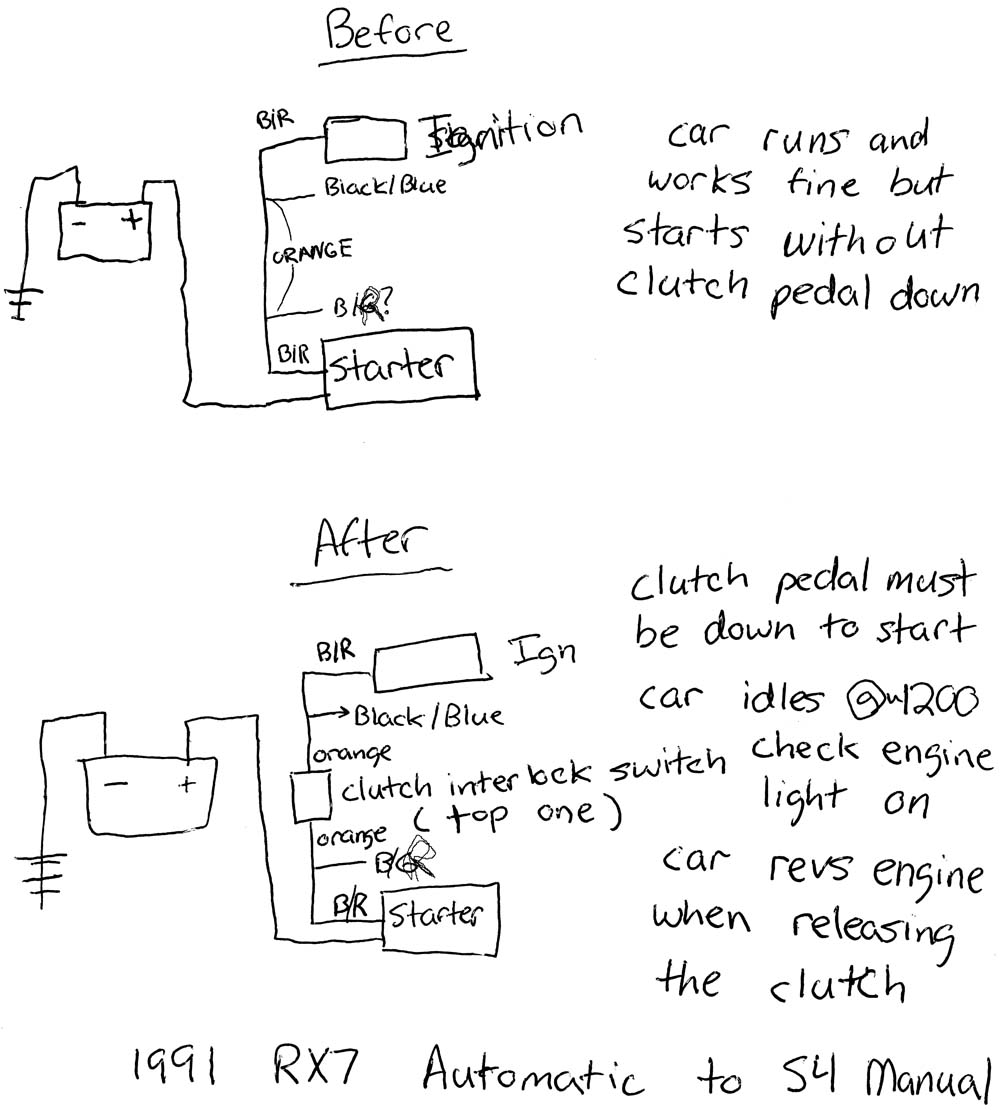
Strange problem when wiring in the Clutch Interlock Switch ... from www.rx7club.com For large machines with numerous doors, individual controller cables are required, making the wiring for safety devices very complicated. Maintenance reminder light reset procedures. Figure 2 exceeds nec requirements, but the additional safety provided by the zero speed switch km2 km2 22 22 km1 km1 a2 a2 reversing contactor transfer contactor, mechanical interlock w.
So what has safety relays to do with safeguarding?
Design conforms to foreign safety standard (ul/csa/tuv). You hubby broke the shift interlock system , a safety system that doesn't allow the gear selector to be moved into a gear. A simple electrical interlocking control diagram is shown below. Redundant integration into safety circuit when wiring several.
Bagikan Artikel ini
Belum ada Komentar untuk "Safety Interlock Wiring Diagram"

Belum ada Komentar untuk "Safety Interlock Wiring Diagram"
Posting Komentar